
 Stone Cutting Machines
 Stone Polishing Machines
 Bridge Saw Machines
 Stone Quarry Cutting Machines
 Stone Block Cutter Machine
 CNC Stone Wire Saw Machine
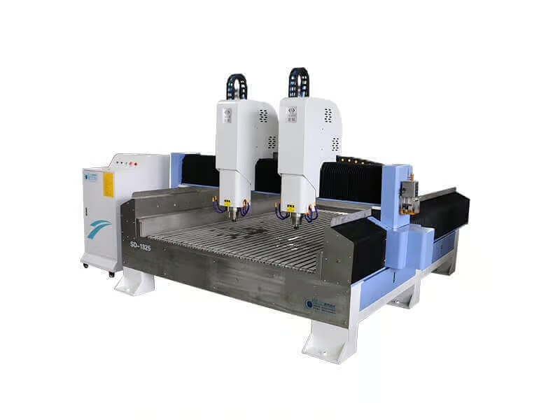 Stone Engraving Machines
 Thin Stone Veneer Saw Machine
 Horizontal Stone Slab Splitting Machine
 Stone Edge Polishing Profiling Machine
 Stone Auxiliary Equipment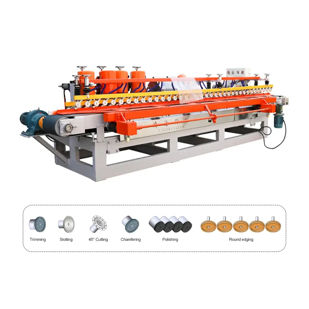
🔬 The Physics of Abrasive Loss
In the world of automated stone fabrication, there is a dangerous misconception that metal-bonded diamond tools are indestructible. The reality lies in the physics of self-sharpening abrasive wear. When cutting through dense materials like quartz or absolute black granite, the metal matrix holding the diamond grit is designed to slowly erode. This exposes fresh, sharp diamonds to the stone. While necessary for cutting efficiency, this continuous erosion inevitably shrinks the absolute diameter of the profiling wheel. If left uncalibrated, the geometric profile carved into the stone will gradually become shallower over hundreds of meters.
🏗️ Scaling Production: A Vancouver Success Story
A major commercial fabrication plant in Vancouver, Canada, was commissioned to produce a 20-meter continuous bar top featuring a complex Ogee edge for a luxury hotel. During the initial run on their horizontal line, the installers noticed a severe problem: the final slab’s profile was 2mm shallower than the first, creating an unacceptable step-joint where the pieces met. By implementing MosCut’s recommended Y-Axis Step Compensation Protocol (involving fixed 500-meter spot checks and 0.5mm micro-advancements), the plant successfully eliminated profile drift, guaranteeing 100% geometric symmetry across massive multi-slab commercial orders.
The Wear Phenomenon: Why Profiles Shrink
Diamond tools are designed to wear. Uncompensated wear is the enemy of precision.The primary culprit of profile drift lies in the very first spindle of your edge polishing machine. In a horizontal continuous line, Spindle No. 1 is typically equipped with a coarse-grit, metal-bonded router bit. This single wheel is responsible for up to 70% of the total raw stock removal. Because it is aggressively plowing through the bulk of the granite to form the initial shape, it wears down at a significantly faster rate than the subsequent honing and polishing resin pads.
As this first shaping wheel loses a fraction of a millimeter in diameter, it stops reaching its designated depth. Consequently, the second and third shaping wheels are forced to remove the excess stone left behind, accelerating their wear as well. This domino effect ultimately results in a “shrunk” or flattened architectural profile that no longer matches your original template.
The Y-Axis Micro-Adjustment: Reclaiming the Profile
A systematic approach to resetting your focal point on a continuous polisher.Step 1: Precision Measurement
Never adjust blindly. Always halt the machine and utilize a rigid stainless steel Profile Template or a digital caliper. Compare the freshly cut edge against the template. If there is a gap between the stone and the inner curve of your template, you must measure the exact depth discrepancy (e.g., the profile is 0.5mm too shallow).
Step 2: Unlocking the Limit Nut
For absolute stability during cutting, the heavy-duty shaping spindles on a horizontal machine are secured by rigid mechanical limit nuts. Before attempting to turn the adjustment handwheel, you must use an industrial wrench to loosen the locking nut, freeing the motor to move along its slide track.
Step 3: Forward Advancement
Consult the dial indicator on the mechanical handwheel. Slowly turn the wheel to advance the spindle motor forward along the Y-axis (towards the stone) by exactly the missing 0.5mm. Once set, firmly re-tighten the limit nut to lock the spindle in place, and run a test piece to verify the new depth.
Reading the Stone: Diagnosing Uneven Wear
Not all wear is symmetrical. Recognize the signs of angular deflection.
The Danger of Asymmetrical Wear
Sometimes the issue isn’t that the entire profile is too shallow; rather, the geometry is distorted. You might notice the top half of the Ogee curve is oversized, while the bottom half barely touched the stone. This phenomenon is known as Asymmetrical Wear.
The Diagnosis: This is rarely a simple Y-axis issue. It typically indicates that the 45-degree or 90-degree tilt angle of the shaping motor has shifted slightly due to long-term industrial vibration, or the slab is not resting 100% flat on the conveyor belt.
The Solution: Pushing the Y-axis forward will only make the distortion worse. You must perform a 3D recalibration. First, verify the conveyor belt is clear of debris. Then, use an angle gauge to reset the spindle motor’s exact tilt angle, and adjust the Z-axis (up/down) to realign the center point of the diamond wheel with the centerline of the stone.
End of Wheel Lifespan: When to Replace vs. Compensate
Pushing a dead wheel leads to shattered stone and burnt motors.
Identifying the Limit
A metal-bonded profiling wheel has a finite working layer (usually 3mm to 5mm thick). There is a critical visual boundary between the abrasive diamond matrix and the underlying Steel Core.
When the wear reaches this steel core, compensation must stop immediately. Pushing a completely bald wheel into solid granite will not cut the stone. Instead, the smooth steel will generate catastrophic friction. This massive heat buildup will scorch engineered quartz, cause natural granite to micro-fracture and shatter, and potentially overload and burn out your 22kW spindle motor.
Operators must implement a Preventative Tooling Schedule—inspecting the wheels visually every week to identify the wear limit before it causes catastrophic machine damage or halts production.
Maintain Perfect Architectural Symmetry
Ensure every piece matches perfectly on massive commercial projects. Equip your fabrication shop with the MosCut Horizontal Continuous Edge Polisher, featuring ultra-precise mechanical handwheels designed for effortless Y-axis calibration and unyielding stability.
View the Horizontal Polisher